Tutorial — First LED
Learn by programming: follow each step, write your own code, then validate with the lab questions and exam. Adapt pins and routines to your board when needed.
What you will build
An assembly program that configures RB0 as output and turns on an LED. This is the foundation for most of the course.
-
1 Create the MPLAB project
Open MPLAB IDE 8.88 → File → New Project. Select PIC18F4550, MPASM compiler, and your programmer (PICkit 2/3) or Simulator if you have no board yet. Create a `.asm` file in the project.Tip: Setup guide: /en/fundamentos/mplab-proteus/
-
2 Write CONFIG directives
At the top of the file declare the processor and disable the watchdog. With a 20 MHz crystal use `FOSC = HS`. These lines do not generate executable code—they tell the assembler how to configure the PIC when programming.LIST P=18F4550 #include <P18F4550.INC> CONFIG FOSC = HS CONFIG WDT = OFF CONFIG LVP = OFF -
3 Set RB0 as output
`TRISB` sets direction: bit `1` = input, bit `0` = output. To drive an LED on RB0 you need that pin as output. Use `BCF TRISB, 0` (clears bit 0). Clear `LATB` first for a known state.inicio: CLRF LATB ; Apaga todas las salidas de PORTB BCF TRISB, 0 ; RB0 como salida -
4 Turn the LED on via LATB
Write to `LATB`, not `PORTB`, to set the output level. `BSF LATB, 0` drives RB0 high. If your LED goes RB0 → resistor → cathode to ground, it should light up.BSF LATB, 0 ; RB0 en alto — LED encendido bucle: GOTO bucle ; El PIC no debe “terminar” -
5 Simulate in Proteus and adapt to your build
Import PIC18F4550, 20 MHz crystal, LED on RB0 with 220–330 Ω resistor. Build in MPLAB → load `.hex` in Proteus. Adapt the pin if your board uses another port: change `TRISB`/`LATB` and the matching bit.Tip: Exercise: move the LED to RB1. Which two lines change?
Before you code — pre-lab
Pre-laboratory — reference research
Introduction to your first assembly program: digital GPIO outputs. Foundation before formal UNEXPO labs.
Q 1 What does the TRISB register do?
TRISB sets each PORTB pin direction:
- Bit = 1 → input (high impedance).
- Bit = 0 → output (driven by LATB/PORTB).
To drive an LED on RB0 use `BCF TRISB, 0` (bit 0 = output). Without TRIS setup the pin may stay input and the LED won't respond.
Q 2 PORTB vs LATB when writing
For digital outputs write LATB (*latch*): the value is stored without read-modify-write issues on PORT when the pin reads external level.
`BSF LATB, 0` drives RB0 high (LED on if cathode to ground with resistor). `BCF LATB, 0` turns it off.
Q 3 LED wiring with resistor
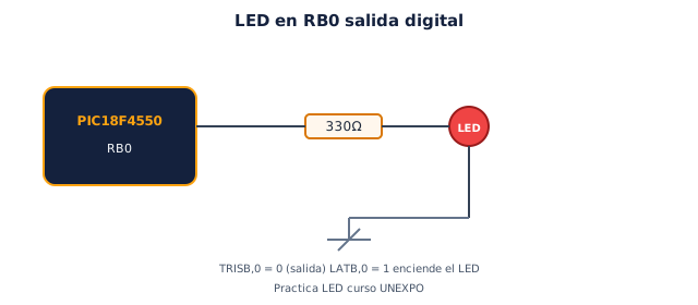
Typical wiring: RB0 → 220–330 Ω resistor → LED anode → LED cathode → GND.
The resistor limits current (~10–15 mA) to protect the LED and stay within the PIC pin limit (~25 mA max per pin; less is better).
This lab is shorter but uses the same design flow (pseudocode, flowchart, exam).
Design your solution
Design before coding
The lab sheet asks for pseudocode and a flowchart before the .ASM. Write yours first, then unlock the reference guide.
- 1. Pseudocode
- 2. Flowchart
- 3. Reference
Write your pseudocode
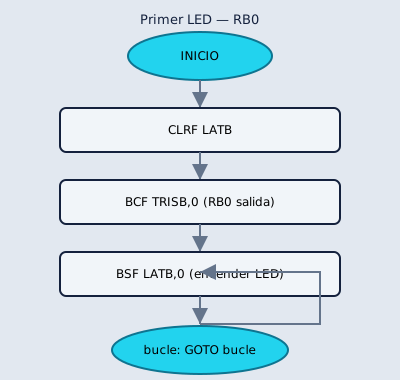
Include: CLRF LATB, BCF TRISB,0, BSF LATB,0 and infinite loop.
0 characters (minimum 80)
Describe your flowchart
On paper or here: list each symbol in order. Your report needs ovals, rectangles, diamonds and the main loop.
0 characters (minimum 60)
My pseudocode draft
My flowchart draft
Reference pseudocode
START
    LATB ← 0
    TRISB.0 ← 0          ; RB0 output
    LATB.0 ← 1           ; LED on
REPEAT FOREVER
    ; (future: blink with delay)
END REPEAT
Reference flowchart
Build and adapt the code
Practica · Beginner
Turn on an LED on RB0
Goal: configure RB0 as output and write a high level to turn on an LED connected correctly with its resistor.
Full reference code
Section titled “Full reference code” LIST P=18F4550 #include <P18F4550.INC>
CONFIG FOSC = HS CONFIG WDT = OFF CONFIG LVP = OFF
ORG 0x0000 GOTO start
start: CLRF LATB ; Clear PORTB outputs BCF TRISB, 0 ; RB0 as output BSF LATB, 0 ; RB0 high
loop: GOTO loop
ENDWhat you should be able to explain
Section titled “What you should be able to explain”- Why
TRISBis used. - Why
BCF TRISB, 0makesRB0an output. - Why the code writes to
LATBand not necessarily toPORTB. - Why the program ends in an infinite loop.
Exercise
Section titled “Exercise”Modify the program so the LED is on RB1. Then explain which lines changed and why.
After building — post-lab
Post-laboratory — reference research
Reflection after assembling and simulating your first program.
Q 1 Why does the program end in an infinite loop (`GOTO bucle`)?
A microcontroller has no OS holding control: after `inicio` the CPU keeps fetching instructions. Without a loop it would run uninitialized memory. `GOTO bucle` keeps the LED state until reset or reprogramming.
Q 2 What would you change to blink the LED every 500 ms?
You must toggle LATB.0 periodically with a delay (~500 ms via nested loops or Timer0). Pseudocode:
`loop: toggle RB0 → wait 500ms → goto loop`
This introduces timing, covered with Timer0 in the course.
Try moving the LED to RB1 and document the line changes.
Check what you learned
Exams by difficulty level
Open each level when you are ready. Basic is public; intermediate and UNEXPO levels require a CALETAS account to submit answers.
Basic Basic level — GPIO 3 questions
TRIS, LAT and LED wiring.
0 of 0 answered
Sign in with CALETAS to sync this result across devices.
Sign in with CALETASIntermediate Intermediate level — Registers 2 questions
PORT vs LAT and main loop.
0 of 0 answered
Sign in with CALETAS to sync this result across devices.
Sign in with CALETASUNEXPO UNEXPO level — Oral explanation 2 questions
Explain each line of the first LED .ASM.
0 of 0 answered
Sign in with CALETAS to sync this result across devices.
Sign in with CALETAS