Tutorial — Practice 2: Keyboard and LCD
Learn by programming: follow each step, write your own code, then validate with the lab questions and exam. Adapt pins and routines to your board when needed.
What you will build
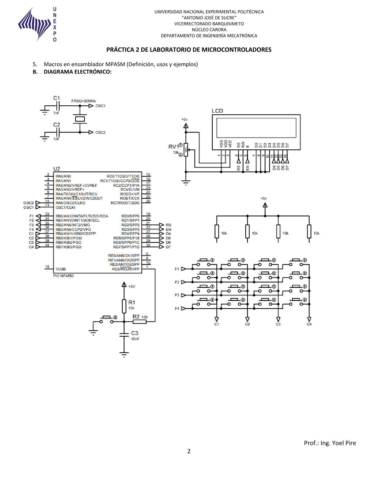
Read a 4x4 matrix keyboard and display pressed keys on a 16x2 LCD in 4-bit mode.
-
1 Project, CONFIG, and digital pins
Create an MPASM project for PIC18F4550 (20 MHz HS). Set `ADCON1 = 0x0F` so PORTB and PORTD are digital. Reserve RAM for the detected key, row/column indices, and delay counters.MOVLW 0x0F MOVWF ADCON1 CLRF nueva_tecla -
2 Set up the 4-bit LCD bus
PORTD carries D4–D7 (RD4–RD7), RS on RD2, E on RD3. Set `TRISD = 0` (all outputs). Write `lcd_nibble`, `lcd_cmd`, and `lcd_dat` routines that send the high nibble, then the low nibble, strobing E.CLRF LATD CLRF TRISD ; LCD salidas ; Pulso E: sube, pequeño retardo, baja lcd_strobe: BSF LATD, 3 ; E = 1 CALL retardo_corto BCF LATD, 3 ; E = 0 RETURNTip: Reference topic: /en/comunicacion/lcd-teclado/
-
3 Initialize the HD44780
Typical 4-bit sequence: >40 ms delay after power-up, then commands `0x33`, `0x32`, `0x28` (2 lines, 4-bit), `0x0C` (display on, cursor off), `0x06` (entry mode). Test by writing KEY: on line 1 before the keyboard logic.lcd_init: CALL retardo_largo MOVLW 0x33 CALL lcd_cmd MOVLW 0x32 CALL lcd_cmd MOVLW 0x28 CALL lcd_cmd MOVLW 0x0C CALL lcd_cmd RETURN -
4 Scan the 4×4 keyboard by rows
Rows RB0–RB3 as outputs, columns RB4–RB7 as inputs with external pull-ups. For each row: drive it low, read PORTB. If a column reads 0, compute the index and look up the character in a 4×4 table (`1`–`9`, `A`–`D`, `*`, `#`).MOVLW 0xF0 MOVWF TRISB ; cols in, rows out tabla_teclas: DB '1','2','3','A' DB '4','5','6','B' DB '7','8','9','C' DB '*','0','#','D' -
5 Enable RB4–RB7 interrupt
Enable RBIE and GIE. In the ISR: check RBIF, run the scan, debounce (20–50 ms), store the key, and clear RBIF by reading PORTB. In the main loop, if there is a new key, write it on LCD line 2 with `lcd_dat`.BCF INTCON2, RBPU BSF INTCON, RBIE BSF INTCON, GIE isr_alta: ; guardar contexto ... BTFSC INTCON, RBIF CALL escanear_tecla ; leer PORTB limpia RBIF ; restaurar contexto / RETFIE -
6 Simulate and test every key
In Proteus verify each key shows the correct character without duplicates. If you see bounce, increase debounce delay. Adapt pins if your section uses a different row/column map—update `TRISB`, the table, and scan masks.
Before you code — pre-lab
Pre-laboratory — reference research
Answers aligned with Practice 2 (Keyboard and LCD, UNEXPO). Use them to research before the lab and write your report in your own words.
Q 1 What is the HD44780 controller and how does it talk to the PIC?
The HD44780 is the standard controller for alphanumeric LCDs (16×2, 20×4, etc.). It uses a parallel bus:
- RS: 0 = command, 1 = character data.
- E: enable strobe to latch data.
- Data: 4-bit mode (high nibble + low nibble) or 8-bit.
In Practice 2 the data bus uses RD4–RD7, RS = RD2, E = RD3. The PIC sends init commands then writes characters to LCD DDRAM.
Q 2 How does a 4×4 matrix keyboard work?
A matrix keyboard has 4 rows and 4 columns (16 keys). To detect a key:
1. Rows as outputs (or driven low) and columns as inputs with pull-ups.
2. Scan each row low and read columns.
3. A 0 on a column means a key at (row, column).
4. A lookup table maps row/column → character ('0'–'9', 'A'–'D', '*', '#').
In the UNEXPO build: rows RB0–RB3, columns RB4–RB7 with 10 kΩ pull-ups.
Q 3 Interrupt on change RB4–RB7 (PORTB)
The PIC18 can interrupt when RB4–RB7 change level:
- INTCON.RBIF — PORTB interrupt flag.
- INTCON.RBIE — enable interrupt.
- INTCON.RBIP — priority (if used).
A key press changes a column and triggers the ISR. The ISR scans the keyboard, debounces, and stores the key. Clear RBIF by reading PORTB before leaving the ISR.
Q 4 LCD.INC library and MPASM macros
The lab requires LCD.INC from the course (Topic 7.1) in 4-bit mode. Typical macros:
- `LCDinit` — HD44780 init sequence.
- `LCDcmd` — send command.
- `LCDchar` — write ASCII character.
- `LCDlinea1` / `LCDlinea2` — set cursor position.
Macros expand at assemble time. In your report explain each macro you use.
Do not copy verbatim. Your report must include your pseudocode, flowchart and keyboard scan explanation.
Design your solution
Design before coding
The lab sheet asks for pseudocode and a flowchart before the .ASM. Write yours first, then unlock the reference guide.
- 1. Pseudocode
- 2. Flowchart
- 3. Reference
Write your pseudocode
Include: 4-bit LCD init, matrix scan, key table, PORTB ISR, debounce and display update.
0 characters (minimum 80)
Describe your flowchart
On paper or here: list each symbol in order. Your report needs ovals, rectangles, diamonds and the main loop.
0 characters (minimum 60)
My pseudocode draft
My flowchart draft
Reference pseudocode
START
    Init LCD (4-bit, 2 lines)
    Config RB0-RB3 outputs, RB4-RB7 inputs
    Enable RB4-RB7 interrupt
    buffer ← "", pos ← 1
REPEAT FOREVER
    IF new_key THEN
        IF key = '#' THEN display buffer on LCD
        ELSE buffer ← buffer + key; write key to LCD
    END IF
END REPEAT

ISR_PORTB:
    scan matrix → key
    debounce 30 ms
    set new_key flag
    clear RBIF
END ISR
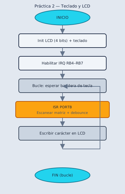
Reference flowchart
Build and adapt the code
Practica · UNEXPO
Lab Practice 2
Control a 16x2 LCD and 4x4 matrix keyboard. Display values entered from the keyboard.
Wiring
Section titled “Wiring”| Device | PIC pins |
|---|---|
| LCD data (4 bit) | RD4-RD7 |
| LCD RS, E | RD2, RD3 |
| Keyboard rows | RB0-RB3 |
| Keyboard columns | RB4-RB7 |
Program requirements
Section titled “Program requirements”- Commented modular MPASM
- RB4-RB7 interrupts for keyboard
- LCD.INC library (4-bit bus) per Topic 7.1
- Pseudocode and flowchart in your report
Reference source code
Section titled “Reference source code”After building — post-lab
Post-laboratory — reference research
Typical closing questions for the Practice 2 report.
Q 1 Why does the LCD use 4-bit mode instead of 8?
4-bit mode saves PIC pins: only 4 data lines (RD4–RD7) plus RS and E, instead of 8 data + control. The HD44780 receives each byte as two nibbles (high, then low). Standard in labs with pin constraints.
Q 2 What problems occur without keyboard debouncing?
Without debouncing, one mechanical press can trigger multiple interrupts or duplicate characters on the LCD. Common fixes: 20–50 ms delay after detection, ignore repeats until release, or filter in software inside the ISR.
Include Proteus screenshots or hardware photos and explain your debounce approach.
Check what you learned
Exams by difficulty level
Open each level when you are ready. Basic is public; intermediate and UNEXPO levels require a CALETAS account to submit answers.
Basic Basic level — Schematic and wiring 4 questions
Questions about the 4-bit LCD and 4×4 keyboard wiring.
0 of 0 answered
Sign in with CALETAS to sync this result across devices.
Sign in with CALETASIntermediate Intermediate level — HD44780 and interrupts 4 questions
LCD controller, matrix scan and RB4–RB7.
0 of 0 answered
Sign in with CALETAS to sync this result across devices.
Sign in with CALETASUNEXPO UNEXPO level — Oral and report 4 questions
Oral exam style: algorithm, debounce and LCD.INC library.
0 of 0 answered
Sign in with CALETAS to sync this result across devices.
Sign in with CALETAS