Tutorial — Practice 8: Serial communication
Learn by programming: follow each step, write your own code, then validate with the lab questions and exam. Adapt pins and routines to your board when needed.
What you will build
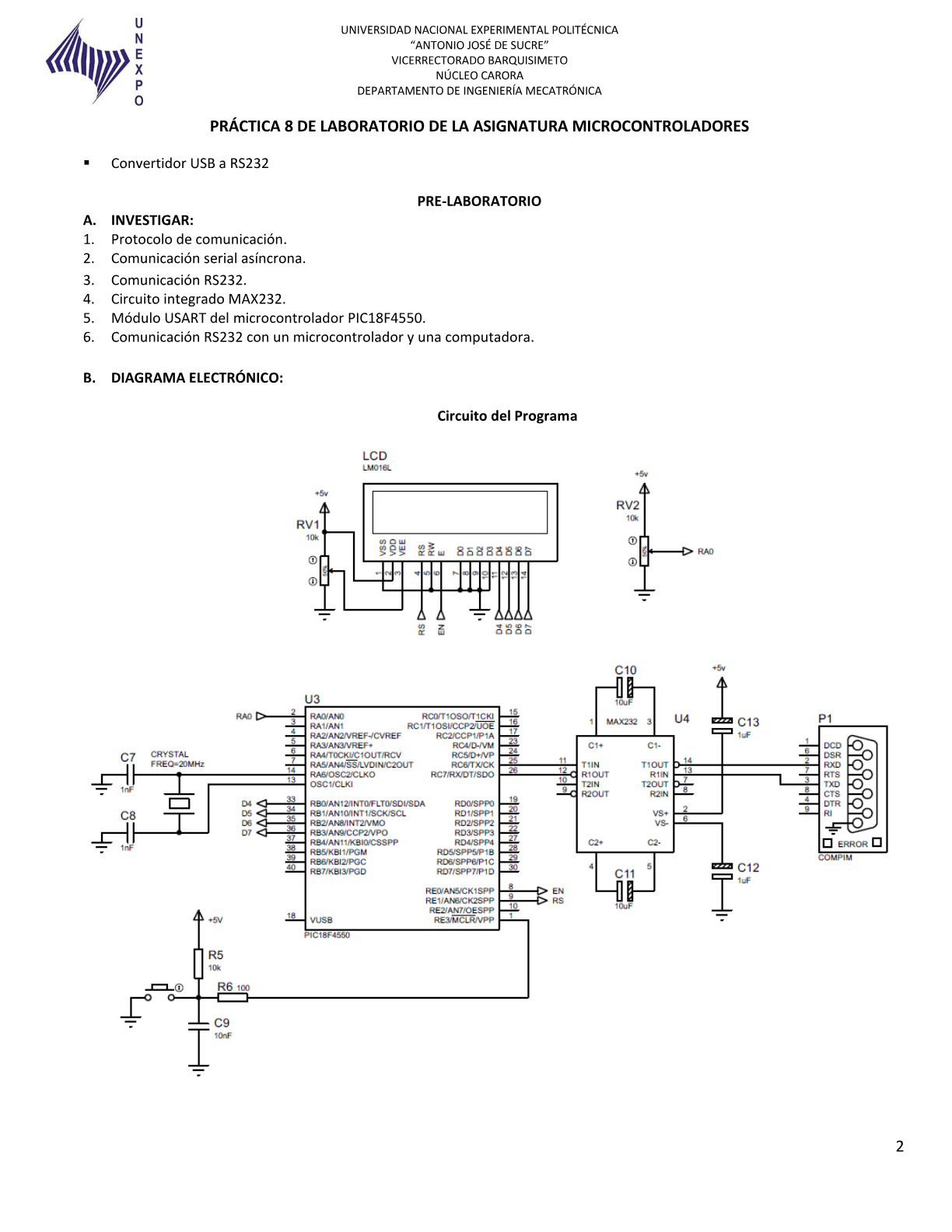
Send and receive UART data at 9600 baud between the PIC and a PC.
-
1 Configure RC6 (TX) and RC7 (RX)
RC7 input (RX), RC6 output (TX). With MAX232: PIC ↔ MAX232 ↔ DB9/USB-serial. `ADCON1 = 0x0F` for digital pins.BSF TRISC, 7 ; RX BCF TRISC, 6 ; TX -
2 Calculate SPBRG for 9600 baud
At 20 MHz with BRGH = 1: `SPBRG = (Fosc / (16 × baud)) - 1` → ~129. Document the calculation in your report. Configure TXSTA (async, BRGH, TXEN) and RCSTA (SPEN, CREN).uart_init: BCF TXSTA, SYNC BSF TXSTA, BRGH MOVLW D'129' MOVWF SPBRG BSF RCSTA, SPEN BSF TXSTA, TXEN BSF RCSTA, CREN RETURNTip: Formulas: /en/comunicacion/uart/
-
3 uart_tx transmit routine
Wait for TXIF = 1, write the byte to TXREG. Send a greeting (`PIC18 UART\r\n`) at startup to confirm the PC receives data.uart_tx: BTFSS PIR1, TXIF GOTO uart_tx MOVWF TXREG RETURN -
4 Echo loop in main
If RCIF = 1, read RCREG (clears flag), send the same byte with `uart_tx`. Open terminal at 9600 8N1. Each key should echo on screen.bucle: BTFSS PIR1, RCIF GOTO bucle MOVF RCREG, W CALL uart_tx GOTO bucle -
5 Test with PC terminal
PuTTY or Tera Term: correct COM, 9600 baud. Garbage means check BRGH/SPBRG or crystal. No data means check MAX232 and crossed TX/RX. Save screenshot for the report.
Before you code — pre-lab
Pre-laboratory — reference research
Research for Practice 8 (Serial communication, UNEXPO). Links to course EUSART.
Q 1 PIC18F4550 EUSART module
The EUSART sends and receives asynchronous serial bytes:
- TXSTA — transmit control (TXEN, BRGH, etc.).
- RCSTA — receive control (SPEN, CREN, RX9).
- SPBRG — baud rate generator.
- TXREG / RCREG — TX / RX buffer.
Pins: RC6 = TX, RC7 = RX. Set `TRISC` for alternate functions and enable SPEN in RCSTA.
Q 2 SPBRG calculation for target baud rate
With BRGH = 1 (high speed, common at 20 MHz):
`SPBRG = (Fosc / (4 × baud)) - 1`
Example: Fosc = 20 MHz, baud = 9600:
`SPBRG = (20_000_000 / (4 × 9600)) - 1 ≈ 520`
For 115200 the value is lower. Show your calculation and percent error in the report.
Q 3 What is the MAX232 for in the schematic?
The PIC uses TTL levels (0–5 V). A PC serial port (RS-232) uses roughly ±12 V. The MAX232 converts TTL ↔ RS-232 using external capacitors. Without it the PC cannot decode the PIC's bits correctly.
RC6 = TX and RC7 = RX are the UART pins in the typical schematic.
Design your solution
Design before coding
The lab sheet asks for pseudocode and a flowchart before the .ASM. Write yours first, then unlock the reference guide.
- 1. Pseudocode
- 2. Flowchart
- 3. Reference
Write your pseudocode
Include: SPBRG calculation, TXSTA/RCSTA setup, TXIF wait, RCIF/RCREG read and optional simple protocol.
0 characters (minimum 80)
Describe your flowchart
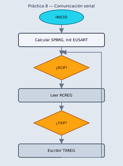
On paper or here: list each symbol in order. Your report needs ovals, rectangles, diamonds and the main loop.
0 characters (minimum 60)
My pseudocode draft
My flowchart draft
Reference pseudocode
START
    Configure EUSART (SPBRG, TXSTA, RCSTA)
    TRISC.6 ← output, TRISC.7 ← input
REPEAT FOREVER
    IF RCIF THEN
        rx_data ← RCREG
        process_command(rx_data)
    END IF
    IF need_tx THEN
        WHILE TXIF = 0 DO
        TXREG ← tx_data
    END IF
END REPEAT
Reference flowchart
Build and adapt the code
Practica · UNEXPO
Lab Practice 8
Establish serial communication between PIC18F4550 and a PC using EUSART. Send and receive data (serial terminal).
Requirements
Section titled “Requirements”- Configure EUSART at 9600 or 115200 baud
- Pins RC6 (TX) and RC7 (RX)
- PC terminal (PuTTY, Tera Term, Arduino Serial Monitor)
- Optional: simple command protocol
Reference source code
Section titled “Reference source code”After building — post-lab
Post-laboratory — reference research
Questions after testing UART with a PC terminal or Proteus.
Q 1 How do you know a byte was transmitted correctly?
Before writing TXREG check TXIF is 1 (transmit buffer empty). After writing, wait until TXIF is 1 again before the next byte. On receive, RCIF means a byte is in RCREG; read RCREG to clear the flag.
Q 2 Typical errors when the terminal shows garbage
Common causes: wrong baud rate (bad SPBRG), BRGH mismatch, TX/RX wiring error, bad MAX232 wiring, or terminal at 9600 while PIC uses 115200. Verify project Fosc (20 MHz HS).
Attach a terminal screenshot showing sent and received data.
Check what you learned
Exams by difficulty level
Open each level when you are ready. Basic is public; intermediate and UNEXPO levels require a CALETAS account to submit answers.
Basic Basic level — UART and schematic 3 questions
EUSART, pins and MAX232.
0 of 0 answered
Sign in with CALETAS to sync this result across devices.
Sign in with CALETASIntermediate Intermediate level — EUSART registers 3 questions
TXSTA, RCSTA, TXIF and RCIF.
0 of 0 answered
Sign in with CALETAS to sync this result across devices.
Sign in with CALETASUNEXPO UNEXPO level — UART oral 2 questions
SPBRG math, errors and terminal test.
0 of 0 answered
Sign in with CALETAS to sync this result across devices.
Sign in with CALETAS