Tutorial — Practice 3: Frequency meter
Learn by programming: follow each step, write your own code, then validate with the lab questions and exam. Adapt pins and routines to your board when needed.
What you will build
Measure frequency with Timer0 as counter, 1 s window via Timer1 ISR, and multiplex three displays.
-
1 Configure PORTD and PORTE for the display
RD0–RD3 send BCD to the 74LS48. RE0–RE3 select the digit (transistors). Configure both ports as outputs. `ADCON1 = 0x0F` keeps RA4/T0CKI digital for the frequency input.MOVLW 0x0F MOVWF ADCON1 CLRF TRISD CLRF TRISE -
2 Timer0 as pulse counter
Configure T0CON: `T0CS = 1` (external counter), 16-bit mode, increment on rising edge at RA4/T0CKI. Clear TMR0H:TMR0L before each measurement.MOVLW B'00111000' MOVWF T0CON CLRF TMR0H CLRF TMR0L -
3 Define the 1-second window
For exactly 1 s, Timer0 counts external pulses. Options: Timer1 every 50 ms (20 ticks = 1 s) in an ISR, or a calibrated `ventana_1s` delay tuned in Proteus. When the window closes, copy TMR0H:TMR0L to `snap` variables—that is your frequency count in Hz.Tip: Official pseudocode in this practice design challenge.
-
4 Convert count to hundreds, tens, and units
After measurement, split the value into three BCD digits (max 999; saturate at 999 on overflow). Store in `centenas`, `decenas`, `unidades` variables for multiplexing. -
5 Multiplex three digits without flicker
In the main loop (or short ISR): enable one digit on RE, put the BCD nibble on RD, wait ~2–5 ms, turn all off, next digit. Repeat at >50 Hz per digit. The eye sees three stable digits.mostrar_digito: ; digito_act = 0..2 ; seleccionar RE, LATD = centenas/decenas/unidades CALL retardo_corto CLRF LATE ; apagar todos RETURN -
6 Calibrate with a known signal
In Proteus connect a generator (e.g. 100 Hz, 1 kHz). Compare reading vs actual value. Tune `ventana_1s` or Timer1 reload until error is acceptable. Document useful range (16-bit counter → ~65 kHz max in 1 s).
Before you code — pre-lab
Pre-laboratory — reference research
Research base for Practice 3 (Frequency meter with multiplexed displays, UNEXPO).
Q 1 How does a frequency meter measure signal frequency?
A frequency meter counts pulses during a known time window:
`frequency = pulse_count / window_time`
Example: 1000 rising edges in 1 second → 1000 Hz. The PIC uses a timer in counter mode for external pulses and another timer for the window.
Q 2 Multiplexed 7-segment display
A multiplexed display shares the segment bus (a–g, dp) and enables one digit at a time via transistors or digit select lines.
- Advantage: fewer pins (one 74LS48 + 3–4 digit lines).
- Requirement: fast refresh (~50 Hz per digit) for persistence of vision.
- In the lab: 74LS48 decoder, transistors per digit, Timer to rotate active digit.
Q 3 Timers as external event counters
Timer0 or Timer1 can count external pulses on T0CKI / T1CKI (per schematic):
- Configure prescaler to extend range if needed.
- Read 16-bit register when the window closes.
- Clear counter at each new measurement.
A 1 s window can use another timer or calibrated loop + interrupts.
Connect course Timer0/Timer1 with measurement window and display refresh.
Design your solution
Design before coding
The lab sheet asks for pseudocode and a flowchart before the .ASM. Write yours first, then unlock the reference guide.
- 1. Pseudocode
- 2. Flowchart
- 3. Reference
Write your pseudocode
Include: Timer0 as counter, Timer1 50 ms tick, CNT_50MS (20×50 ms = 1 s), multiplexing and the ISR (save/restore context).
0 characters (minimum 80)
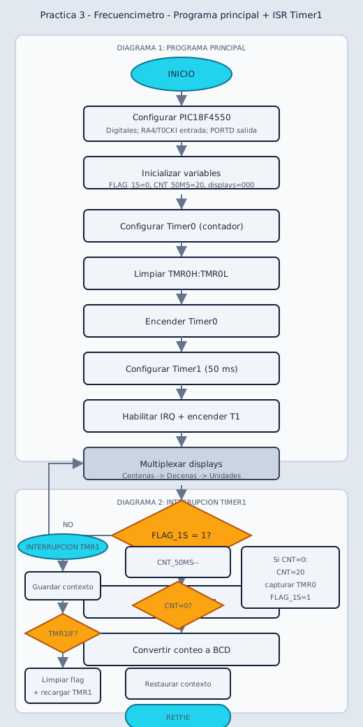
Describe your flowchart
On paper or here: list each symbol in order. Your report needs ovals, rectangles, diamonds and the main loop.
0 characters (minimum 60)
My pseudocode draft
My flowchart draft
Reference pseudocode
START

Configure the PIC18F4550.
Set analog pins as digital.
Configure RA4/T0CKI as the frequency input.
Configure PORTD as output for the 74LS48 and digit select transistors.

Initialize variables:
    FLAG_1S ← 0
    CNT_50MS ← 20
    HUNDREDS ← 0
    TENS ← 0
    UNITS ← 0

Configure Timer0:
    External counter mode.
    Input on RA4/T0CKI.
    16-bit mode.
    No prescaler.
    Count on rising edge.

Clear TMR0H and TMR0L.
Turn on Timer0.

Configure Timer1:
    Internal timer mode.
    Prescaler 1:8.
    Preload for 50 ms interrupts.

Enable Timer1 interrupt.
Enable peripheral and global interrupts.
Turn on Timer1.

REPEAT FOREVER

    Multiplex displays:
        Show hundreds.
        Short delay.
        Turn off displays.

        Show tens.
        Short delay.
        Turn off displays.

        Show units.
        Short delay.
        Turn off displays.

    IF FLAG_1S = 1 THEN

        FLAG_1S ← 0

        Convert captured Timer0 count to BCD.

        IF count > 999 THEN
            HUNDREDS ← 9
            TENS ← 9
            UNITS ← 9
        ELSE
            Split count into hundreds, tens, and units.
        END IF

    END IF

END REPEAT

TIMER1 INTERRUPT

Save context.

IF the interrupt was caused by Timer1 THEN

    Clear Timer1 interrupt flag.
    Reload Timer1 for another 50 ms.

    CNT_50MS ← CNT_50MS - 1

    IF CNT_50MS = 0 THEN

        CNT_50MS ← 20

        Stop Timer0.
        Read TMR0L and TMR0H.
        Store the measured pulse count.
        Clear TMR0H and TMR0L.
        Start Timer0 again.

        FLAG_1S ← 1

    END IF

END IF

Restore context.
Return from interrupt.
Reference flowchart
Build and adapt the code
Practica · UNEXPO
Lab Practice 3
Frequency meter with multiplexed 7-segment displays. Use timers for the measurement window and display refresh.
Key concepts
Section titled “Key concepts”- Timer as external pulse counter
- Display multiplexing to save pins
- Visual persistence with fast refresh (~50 Hz per digit)
- Calculation: frequency = count / window time
Reference source code
Section titled “Reference source code”After building — post-lab
Post-laboratory — reference research
Analysis questions after implementing the frequency meter.
Q 1 What error does slow multiplex refresh cause?
If refresh is too slow (< ~30 Hz per digit), visible flicker appears. If refresh blocks measurement too long, the count window distorts. Use short periodic interrupts for multiplexing without blocking pulse counting.
Q 2 Measurement limits with a 16-bit counter
A 16-bit counter maxes at 65535. With a 1 s window, max frequency without overflow is ~65 kHz (theoretical). Above that use a prescaler or shorter window. State your design's useful range in the report.
Compare measured frequency in Proteus with the configured signal generator.
Check what you learned
Exams by difficulty level
Open each level when you are ready. Basic is public; intermediate and UNEXPO levels require a CALETAS account to submit answers.
Basic Basic level — Concept and schematic 3 questions
Frequency measurement and multiplexed displays.
0 of 0 answered
Sign in with CALETAS to sync this result across devices.
Sign in with CALETASIntermediate Intermediate level — Timers and calculation 3 questions
Measurement window, counter and refresh.
0 of 0 answered
Sign in with CALETAS to sync this result across devices.
Sign in with CALETASUNEXPO UNEXPO level — Full design 3 questions
Oral on multiplexing, range and measurement errors.
0 of 0 answered
Sign in with CALETAS to sync this result across devices.
Sign in with CALETAS