Config bits and configuration word
The configuration word (also called config bits or fuses) sets hardware options the PIC applies at power-on, before running your program: oscillator source, watchdog, MCLR behavior, whether ports start digital, and more.
This page completes the Foundations block with MPASM assembly: there you saw CONFIG at the top of the .ASM and the sandwich layout; here you learn what the configuration word is, what each bit means, and how it ties to the UNEXPO lab minimum system.
What is the configuration word
Section titled “What is the configuration word”In the course you will hear configuration word, config bits, and fuses — the same idea with different names: a fixed block of bits that tells the PIC how to start before your programa: runs.
Step 1 — A group of bits, not a program
Section titled “Step 1 — A group of bits, not a program”The configuration word is not instructions the CPU runs with MOVLW, GOTO, or CALL. It is a hardware switch pack stored in a special chip area:
| Configuration word | Your Flash program | |
|---|---|---|
| What it is | Startup bits (oscillator, WDT, MCLR…) | Instructions the CPU executes |
| When it acts | At power-on or after reset | Line by line while running |
| You define it with | CONFIG directives in .ASM | Code under ORG / labels |
| Changes at runtime | No (unless reprogramming) | Yes — your code modifies SFRs |
Think of it as factory setup for the stage: crystal, reset, and watchdog are chosen before main; then your assembly works on registers (TRISB, LATB…).
Step 2 — You write it with CONFIG in the .ASM
Section titled “Step 2 — You write it with CONFIG in the .ASM”Each CONFIG line sets one part of the word. MPASM maps the name (FOSC, WDT…) and value (HS, OFF…) to the actual PIC18F4550 bit:
CONFIG FOSC = HS ; part of the word: high-speed oscillator CONFIG WDT = OFF ; part of the word: watchdog off CONFIG LVP = OFF ; part of the word: RB5 freeThis is not a literal inside an instruction (like MOVLW D'10'). It is a directive: it talks to the assembler, not to the CPU at run time.
Step 3 — MPASM packs it into the .HEX
Section titled “Step 3 — MPASM packs it into the .HEX”When you build, the .HEX carries two things:
.HEX file ├── Program code (executable Flash) └── Configuration word (startup bits)That is why in MPLAB and Proteus you load one .HEX: Proteus and the programmer store program and configuration word together. Without a CONFIG block, the chip may use defaults different from the lab.
Step 4 — The PIC applies it at power-on
Section titled “Step 4 — The PIC applies it at power-on”Sequence when you apply 5 V:
Power applied (POR) ↓ PWRT (if CONFIG PWRT = ON) PIC reads configuration word ↓ FOSC, WDT, PBADEN, MCLRE… are fixed PC = 0000H → runs ORG 0x0000 ↓ GOTO programa ; jump to main; ...programa: ; destination — your code starts hereIf the program “does not start”, check word + hardware before debugging LATB: supply → crystal/FOSC → MCLR/MCLRE → LVP/PBADEN → only then code.
Key concepts — equivalent names
Section titled “Key concepts — equivalent names”| Concept | Explanation |
|---|---|
| Configuration word | The full block of startup bits |
| Config bits / fuses | Each bit (or group) inside that word |
CONFIG directive | How you write those bits in .ASM |
| Configuration memory | Where they are stored on chip (not executable Flash) |
Think of config bits as factory switches you choose once when building/programming. If WDT = ON and your program never runs CLRWDT, the PIC will reset on its own even when your logic looks fine.
Where it goes in the sandwich .ASM
Section titled “Where it goes in the sandwich .ASM”It belongs in the top layer, after LIST and #include, before the reset vector and code — same as Assembly — anatomy:
; ══ TOP — header + configuration word ════════════════        LIST    P=18F4550        #include <P18F4550.INC>
        CONFIG  FOSC = HS        CONFIG  WDT  = OFF        CONFIG  LVP  = OFF        CONFIG  MCLRE = ON        CONFIG  PBADEN = OFF        CONFIG  BOR  = OFF        CONFIG  PWRT = ON
; ── Reset vector ──────────────────────────────────────        ORG     0x0000        GOTO    programa         ; jump to main (at bottom)
; ══ MIDDLE — subroutines (if any) ═════════════════════; ...
; ══ BOTTOM — main program ════════════════════════════programa:        BCF     TRISB, 0        BSF     LATB, 0loop:        GOTO    loop               ; jump → destination loop: (line above)
        END
In MPLAB v8 you can also edit them via Configure → Configuration Bits, but in the UNEXPO course you usually declare them in .ASM so the report and .HEX match.
Each config bit in detail
Section titled “Each config bit in detail”FOSC — clock source (oscillator)
Section titled “FOSC — clock source (oscillator)”Selects where the execution clock comes from.
| Typical value | Meaning | In this course |
|---|---|---|
HS | High-Speed — external crystal (4–20 MHz+) | Use with 20 MHz crystal |
XT | Low/medium speed crystal | Less common on F4550 |
INTIO / RC | Internal oscillator | No external crystal |
EC / ECM | External clock on a pin | Special cases |
With FOSC = HS you must wire the crystal + capacitors of the minimum system. Without a crystal (or bad wiring), the PIC does not run at the expected speed — or does not start at all.
With a 20 MHz crystal in HS (UNEXPO course):
| Quantity | Typical value | Formula / note |
|---|---|---|
| Fosc | 20 MHz | Oscillator frequency (crystal) |
| Tcy (instruction cycle) | 200 ns | Tcy = 4 / Fosc = 4 / 20 MHz |
| MIPS (order of magnitude) | ~5 | 1 / Tcy in million instructions/s |
That Fosc is set by the configuration word (FOSC = HS) and the physical crystal — they must match. In Proteus and on the board, the PIC clock must reflect 20 MHz if you use this template.
WDT — Watchdog Timer
Section titled “WDT — Watchdog Timer”| Value | Effect |
|---|---|
OFF | Watchdog disabled — recommended while learning |
ON | If you do not reset the WDT with CLRWDT in time, the PIC resets |
In learning labs almost always WDT = OFF. If left ON without CLRWDT in long loops, the program “restarts by itself” and looks like a mysterious bug.
LVP — Low Voltage Programming
Section titled “LVP — Low Voltage Programming”| Value | Effect |
|---|---|
OFF | Normal programming; RB5 free as GPIO |
ON | Low-voltage programming mode — RB5 reserved for programming |
In UNEXPO labs use LVP = OFF. With LVP = ON, RB5 may not behave as expected on your breadboard.
MCLRE — MCLR / reset pin
Section titled “MCLRE — MCLR / reset pin”| Value | Effect |
|---|---|
ON | MCLR pin active as reset (with external pull-up) |
OFF | MCLR can act as a digital pin (uncommon in this course) |
With MCLRE = ON you wire 10 kΩ from MCLR to VDD and a button to GND for manual reset — part of the minimum system.
PBADEN — analog PORTA/B at startup
Section titled “PBADEN — analog PORTA/B at startup”| Value | Effect |
|---|---|
OFF | RA0–RA3 and RB0–RB4 start as digital |
ON | Those pins may start in analog mode |
For GPIO and the first LED use PBADEN = OFF. If ON, reading/writing pins can fail until you configure ADCON1 — a typical lab mistake.
BOR — Brown-Out Reset
Section titled “BOR — Brown-Out Reset”| Value | Effect |
|---|---|
OFF | No automatic reset on VDD drop |
ON | Reset if supply voltage falls too low |
Many course builds use BOR = OFF. With ON, 5 V supply variations can cause unexpected resets.
PWRT — Power-up Timer
Section titled “PWRT — Power-up Timer”| Value | Effect |
|---|---|
ON | Short delay at power-on so supply stabilizes |
OFF | No extra delay |
PWRT = ON is good practice with HS crystal and decoupling caps.
Summary — course template (20 MHz)
Section titled “Summary — course template (20 MHz)”Block ready to copy in the top layer of all your .ASM files:
CONFIG FOSC = HS ; External high-speed crystal CONFIG WDT = OFF ; No watchdog (learning) CONFIG LVP = OFF ; RB5 free; normal programming CONFIG MCLRE = ON ; MCLR reset enabled CONFIG PBADEN = OFF ; Digital ports at startup CONFIG BOR = OFF ; No brown-out reset CONFIG PWRT = ON ; Power-up delayMinimum system — hardware that goes with config bits
Section titled “Minimum system — hardware that goes with config bits”Config bits do not replace the circuit. With FOSC = HS and MCLRE = ON you need the Topic 2 (UNEXPO) wiring:
| Component | Typical value | Function |
|---|---|---|
| PIC18F4550 | — | Microcontroller |
| Crystal | 20 MHz | Main clock (with FOSC = HS) |
| Crystal caps | C1, C2 to ground (see datasheet / lab sheet) | Oscillator load — see Topic 2 diagram |
| MCLR pull-up | 10 kΩ to VDD | Stable reset (MCLRE = ON) |
| Reset button | MCLR to GND | Manual reset |
| Supply | 5 V (VDD/VSS) | PIC power |
| Decoupling | 100 nF (0.1 µF) near PIC | Filters VDD noise |
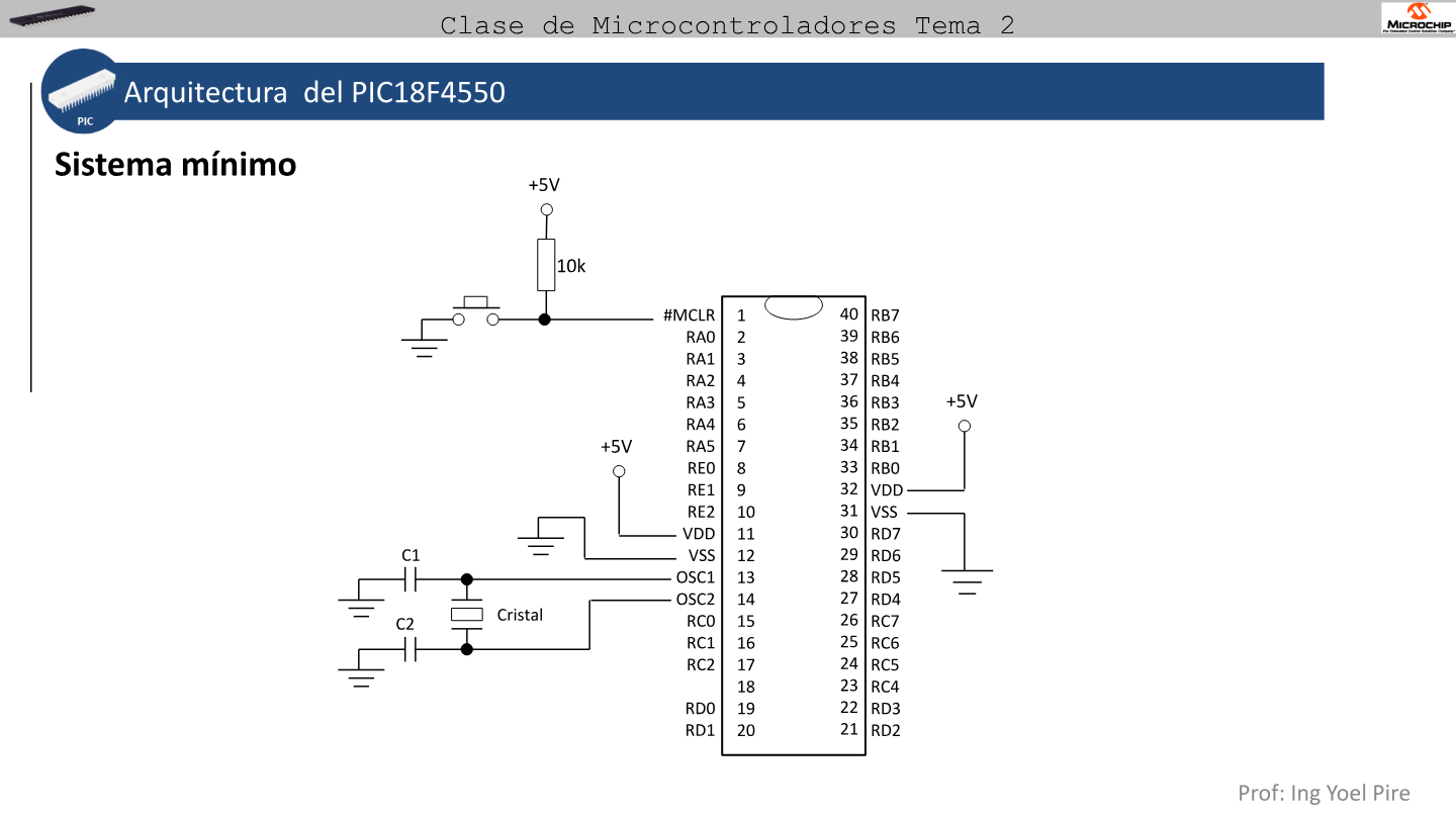
Link to Assembly — LED example: the .ASM configures software (TRISB, LATB); config bits and the crystal configure hardware so that software can run.
Practica · UNEXPO
Lab Practice 1 pre-lab
Research minimum-system wiring, explain PIC18F4550 ports, and draw the schematic including crystal, MCLR, and capacitors before breadboarding. Note on the diagram that FOSC = HS and MCLRE = ON.
Reset types on the PIC18
Section titled “Reset types on the PIC18”The PIC can restart for several reasons. Config bits control some; others come from hardware or code:
| Type | Cause | Config bit link |
|---|---|---|
| Power-On Reset (POR) | VDD turned on | Always on power-up |
| Power-up Timer (PWRT) | Delay after POR | PWRT = ON/OFF |
| MCLR | Low pulse on MCLR pin | MCLRE = ON |
| Watchdog (WDT) | WDT not cleared in time | WDT = ON + missing CLRWDT |
| Brown-Out (BOR) | VDD below threshold | BOR = ON/OFF |
| Software reset | RESET instruction | From your code |
Mental power-on flow:
Apply 5 V ↓ POR (+ PWRT if ON) Config bits applied (FOSC, PBADEN…) ↓ PC = 0x0000 → GOTO start (your ORG)If the program “does not start”, check in this order: supply and decoupling → crystal and FOSC → MCLR and MCLRE → LVP/PBADEN → only then Flash code.
Config bits vs SFR registers
Section titled “Config bits vs SFR registers”| Config bits | SFR registers (TRISB, INTCON…) | |
|---|---|---|
| When applied | At power-on / after reset | On each instruction in your program |
| Where defined | CONFIG directives in .ASM | Runtime instructions |
| Change at runtime | No (unless reprogramming) | Yes — your code modifies them |
| Example | FOSC = HS | BCF TRISB, 0 |
Config bits set the stage; your assembly program works on registers once the PIC is already running.
Ejercicio · Parcial
Diagnose the problem
A classmate programs this .ASM with a correctly wired 20 MHz crystal, but RB0 never changes and Proteus simulation also misbehaves:
CONFIG FOSC = INTIO CONFIG WDT = ON CONFIG PBADEN = ONLikely causes:
FOSC = INTIO— code/hardware expect external HS crystal, but config selects internal oscillator → clock mismatch.WDT = ON— noCLRWDT→ continuous reset.PBADEN = ON— RB0 may start analog → digital GPIO fails.
Typical course fix:
CONFIG FOSC = HS CONFIG WDT = OFF CONFIG PBADEN = OFFCommon mistakes
Section titled “Common mistakes”- Forgetting the
CONFIGblock: the.HEXmay use defaults different from the lab. - Wrong
FOSC: crystal wired butFOSC = INTIO(or vice versa) → no stable clock. WDT = ONwithoutCLRWDT: PIC resets itself in loops.LVP = ON: RB5 reserved for programming — breadboard conflicts.PBADEN = ON: pins “dead” as digital until ADC/analog setup.- Confusing CONFIG with code:
CONFIGlines do not replaceBCF TRISB, 0or turn on LEDs by themselves. - Crystal without capacitors: even with
FOSC = HS, the oscillator may not start.
Exam-style questions
Section titled “Exam-style questions”What is the configuration word?
The startup bit block that sets oscillator, WDT, MCLR, pin modes at power-on, etc. You define it with CONFIG in .ASM and it is programmed with the .HEX — not executable code.
Where are config bits stored?
In the PIC’s configuration memory, not in normal executable Flash.
What does CONFIG WDT = OFF do?
Disables the watchdog timer so the PIC does not reset on WDT timeout.
Why FOSC = HS with a 20 MHz crystal?
Selects high-speed external crystal mode, matching the course minimum system.
What problem does PBADEN = ON cause in a first GPIO program?
Several PORTA/PORTB pins may start as analog, blocking correct digital read/write.
Configuration bits
Based on: PIC18LF4455-I-PT.PDF
0 of 0 answered
Sign in with CALETAS to sync this result across devices.
Sign in with CALETAS