Timer 0
Timer0 is the first timer in the course (Topic 8). It provides precise delays (replacing empty loops), counts external pulses on RA4/T0CKI, and generates periodic interrupts on overflow. You will combine it with Interrupts in Practice 3 (frequency meter) and Practice 5.
With a 20 MHz crystal and FOSC = HS (config bits), the internal timer clock is Fosc/4 = 5 MHz — the basis of all Topic 8 formulas.
What Timer0 does
Section titled “What Timer0 does”Timer0 operates in two main modes:
| Mode | T0CON.T0CS | Clock input | Typical use |
|---|---|---|---|
| Timer | 0 | Fosc/4 (internal) | Delays, LED blink |
| Counter | 1 | Pulses on RA4/T0CKI | Count external events |
Step 1 — The counter increments automatically
Section titled “Step 1 — The counter increments automatically”You write an initial value in TMR0L (and TMR0H if 16 bit). With TMR0ON = 1, hardware increments the counter each clock cycle (divided by prescaler). On 255 → 0 (8 bit) or 65535 → 0 (16 bit), overflow occurs and TMR0IF = 1.
Step 2 — Prescaler
Section titled “Step 2 — Prescaler”The prescaler slows the count. Values in T0CON.PS2:PS0: 1:2, 1:4, …, 1:256. Higher prescaler → longer time until overflow with the same initial value.
Step 3 — 8 bit vs 16 bit
Section titled “Step 3 — 8 bit vs 16 bit”| Mode | Register | Max N | Max time @ 20 MHz, PS 1:256 |
|---|---|---|---|
8 bit (T08BIT = 1) | TMR0L | 256 | ~13.1 ms |
16 bit (T08BIT = 0) | TMR0H:TMR0L | 65536 | ~3.36 s |
For 2 seconds you need 16 bit + prescaler 1:256.
Step 4 — Polling or interrupt
Section titled “Step 4 — Polling or interrupt”| Method | Code | When |
|---|---|---|
| Polling | BTFSS INTCON, TMR0IF in loop | One-shot delay, simple code |
| Interrupt | ISR at ORG 0x0008, TMR0IE + GIE | Background blink, frequency meter |
ISR details: Interrupts — Timer0.
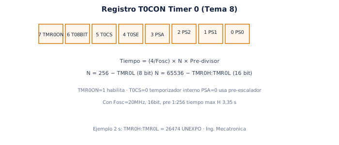
T0CON register
Section titled “T0CON register”| Bit | Name | Function |
|---|---|---|
| 7 | TMR0ON | 1 = Timer active |
| 6 | T08BIT | 1 = 8 bit; 0 = 16 bit |
| 5 | T0CS | 0 = internal Fosc/4; 1 = external T0CKI |
| 4 | T0SE | Active edge in counter mode (0 = rising) |
| 3 | PSA | 0 = prescaler assigned to Timer0 |
| 2–0 | PS2:PS0 | Prescaler 1:2 to 1:256 |
Example MOVLW B'00000111' → 16 bit, internal, prescaler 1:256:
TMR0ON=0 (off while configuring) T08BIT=0 → 16 bit T0CS=0 → internal timer PSA=0, PS=111 → prescaler 1:256Calculate N for a delay
Section titled “Calculate N for a delay”Goal: 2 s with Fosc = 20 MHz, prescaler 1:256.
  Time = (4 / Fosc) × N × PS  2 s    = (4 / 20×10⁶) × N × 256  N      = 2 / [(4/20×10⁶) × 256] = 39062 counts
  Initial value = 65536 − 39062 = 26474 = 0x676A  TMR0H = 0x67 , TMR0L = 0x6A
Check: N = 65536 − 26474 = 39062 ✓
Example: 2 seconds with 20 MHz crystal
Section titled “Example: 2 seconds with 20 MHz crystal”Polling — reusable subroutine:
CONFIGURAR_TIMER_0:        MOVLW   B'00000111'     ; 16 bit, internal, PS 1:256        MOVWF   T0CON        MOVLW   B'01100111'     ; TMR0H = 0x67        MOVWF   TMR0H        MOVLW   B'01101010'     ; TMR0L = 0x6A        MOVWF   TMR0L        RETURN
RETARDO_TMR0_2S:        BCF     INTCON, TMR0IF  ; clear old flag        BSF     T0CON, TMR0ON   ; start timerespera_overflow:        BTFSS   INTCON, TMR0IF  ; wait for overflow        GOTO    espera_overflow ; jump → loop until TMR0IF=1        BCF     T0CON, TMR0ON   ; stop timer        BCF     INTCON, TMR0IF  ; clear flag        RETURN
Use from programa::
CALL CONFIGURAR_TIMER_0 CALL RETARDO_TMR0_2S BSF LATB, 0 ; action after 2 sCounter mode — pulses on RA4
Section titled “Counter mode — pulses on RA4”To count external pulses (e.g. frequency meter — Practice 3):
BSF TRISA, 4 ; RA4 / T0CKI input MOVLW B'00100000' ; T0CS=1, external counter MOVWF T0CON CLRF TMR0H CLRF TMR0L BSF T0CON, TMR0ON ; each pulse on T0CKI increments the counterMeasurement window: combine Timer0 as counter with Timer1 as time window — details in Practice 3.
Common mistakes
Section titled “Common mistakes”| Mistake | Symptom |
|---|---|
| Forget to clear TMR0IF before waiting | Immediate or unpredictable delay |
| 8 bit for long delay | Overflow too fast (~13 ms max with PS 1:256) |
| Wrong Fosc in formula | Times scaled wrong (check crystal and Proteus) |
| Do not stop TMR0ON when reloading in ISR | Extra counts during reload |
Next step
Section titled “Next step”- Timer 1 and Timer 2 — 16 bit, PR2, PWM base
- Practical guide — Interrupts — blink with ISR
- Practice 3 — Frequency meter
Exam-style questions
Section titled “Exam-style questions”What does TMR0IF = 1 indicate?
Timer0 overflowed (FF→00 or FFFF→0000 depending on mode).
What is the maximum time in 8 bit, Fosc = 20 MHz, PS = 1:256?
Time = (4/20×10⁶) × 256 × 256 = 13.1072 ms
Where is Timer0 prescaler configured?
In T0CON (PSA and PS2:PS0 bits).
Ejercicio · Parcial
Calculate maximum 8-bit time with Fosc=20MHz and prescaler 1:256
Time = (4/20MHz) × 256 × 256 = 13.1072 ms per Topic 8 of the Microcontrollers course (UNEXPO).
Timer 0
Based on: Clase Tema 8. Timer.pdf
0 of 0 answered
Sign in with CALETAS to sync this result across devices.
Sign in with CALETAS