Basic architecture
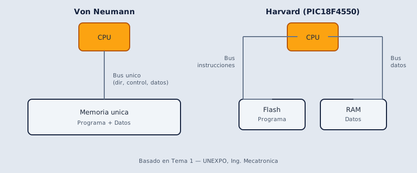
The PIC18F4550 uses a Harvard-style architecture, where program memory and data memory are separated. This allows the microcontroller to fetch instructions and handle data through different spaces.
Important elements
Section titled “Important elements”| Element | Function |
|---|---|
WREG | Working register. Many operations go through it. |
STATUS | Stores flags such as zero, carry, and negative. |
SFR | Special function registers used to control peripherals. |
GPR | General purpose registers used as variables. |
BSR | Selects the memory bank to access registers. |
PC | Program counter. Points to the next instruction. |
The table is a quick reference. Below you will find detailed explanations with examples from real lab work.
Each element in detail
Section titled “Each element in detail”WREG — working register
Section titled “WREG — working register”This is the CPU accumulator: an 8-bit register (one byte, values 0 to 255 — see What 8-bit means) where most arithmetic and logic operations happen before the result is stored somewhere else.
Think of it as the processor’s temporary hand: pick up a value, operate on it, then place it in a register or variable.
MOVLW D'5' ; load 5 into WREGADDLW D'3' ; WREG = 5 + 3 → WREG is 8MOVWF counter ; copy WREG to GPR 'counter'Without WREG you could not use MOVLW, add numbers, or move data between registers with most PIC18 instructions.
STATUS — result flags
Section titled “STATUS — result flags”After many operations, the PIC stores flags in STATUS. Each flag is one bit: either 1 (set/active) or 0 (clear/inactive). On an exam you need to know what each value means, not just the name.
| Bit | Name | What it measures |
|---|---|---|
| 0 | C | Carry |
| 1 | DC | Digit carry (low nibble) |
| 2 | Z | Zero result |
| 4 | OV | Signed overflow |
| 7 | N | Result sign (bit 7) |
What active (= 1) vs inactive (= 0) means
Section titled “What active (= 1) vs inactive (= 0) means”| Flag | = 1 (active) | = 0 (inactive) |
|---|---|---|
| Z | The operation result is zero | The result is not zero |
| C | There was carry past bit 7 (in addition: value exceeds 255 in unsigned 8 bits) | No carry out of the byte |
| DC | There was carry in the low nibble (bit 3 → 4) | No digit carry |
| N | Bit 7 of the result is 1 → negative number in two’s complement (signed) | Bit 7 is 0 → not negative in signed 8 bits |
| OV | Signed overflow: result does not fit in -128 to +127 | Signed operation was valid |
Numeric example with Z — is counter zero? The PIC has no CMP (compare) instruction; you compare by operating and reading the Z flag in STATUS:
MOVLW D'0' ; WREG = 0 (what we compare against)XORWF counter, W ; XOR counter and WREG bit by bit → result in W ; (XOR gate: matching bits → 0, different bits → 1) ; counter unchanged; only W and flags update ; ; if counter = 0: every bit matches WREG ; → result 00000000 → Z = 1 (active) ; if counter = 5: some bits differ from zero ; → result 00000101 → Z = 0 (inactive)Example with C after addition. WREG holds only 8 bits (2⁸ = 256 values: 0 to 255); if the sum exceeds 255, what does not fit is recorded in C and W keeps the remainder:
MOVLW D'200' ; WREG = 200ADDLW D'100' ; 200 + 100 = 300 ; 300 > 255 → does not fit in 8 bits ; 256 overflows (one full byte) → C = 1 (carry) ; WREG holds: 300 - 256 = 44You use flags to make decisions with conditional branches:
MOVLW D'0' ; reference: compare against 0XORWF counter, W ; counter == WREG? → if equal, result 0, Z=1BTFSS STATUS, Z ; skip if Z=1 (counter was 0)GOTO continue ; if Z=0 → jump to destinationGOTO handle_zero ; if Z=1 → jump to destinationhandle_zero: ; counter was 0 ...continue: ; counter was not 0 ...BTFSC skips when the flag is 0; BTFSS skips when it is 1.
On an exam: “How do you know an operation gave zero?” → Z = 1. “How do you know an addition overflowed past 255?” → C = 1.
SFR — special function registers
Section titled “SFR — special function registers”SFRs (Special Function Registers) control internal hardware: ports, timers, ADC, UART, interrupts, and more. Each bit or byte has a fixed meaning defined by Microchip.
Real example — turn on an LED on RB0. To change one bit of an SFR without touching the others, the PIC uses BCF (Bit Clear File → sets the bit to 0) and BSF (Bit Set File → sets the bit to 1):
BCF TRISB, 0 ; TRISB is an SFR, bit 0 → force that bit to 0 ; (bits 1..7 of TRISB stay unchanged) ; on TRISB: 0 = output → RB0 becomes an outputBSF LATB, 0 ; LATB is an SFR, bit 0 → force that bit to 1 ; (bits 1..7 of LATB stay unchanged) ; RB0 goes high → LED onYou are not writing the whole byte: BCF/BSF only change the bit you specify; the rest of the register stays the same. TRISB and LATB are fixed hardware names — you do not invent them.
Other SFRs you will use soon: INTCON (interrupts), TMR0 (Timer0), ADCON0 (ADC).
GPR — general purpose registers
Section titled “GPR — general purpose registers”GPRs are RAM bytes your program uses as variables: counters, temporaries, state-machine states, and so on. They do not control hardware directly; they hold data.
With counter RES 1 you do two things at once: the name (counter) defines the variable — a symbol you will use in code — and RES 1 reserves 1 byte of RAM for it. Later when you write INCF counter, F, the assembler already knows which address that is.
; In the variable section:counter     RES     1       ; define 'counter' and reserve 1 byte in RAM
; In code:INCF    counter, F         ; counter = counter + 1MOVF    counter, W         ; copy counter to WREGDECFSZ  counter, F         ; decrement; if zero, skip next instructionGOTO    wait
The key difference from an SFR: counter is yours — you name it and use it however you need. TRISB is not — its name and function come from the hardware.
BSR — bank selector
Section titled “BSR — bank selector”Both SFRs and GPRs live in data RAM, split into banks (0 through 15). The BSR register tells the CPU which bank you are in when you access an address.
Many SFRs (TRISB, LATB, INTCON…) live in the access bank and do not require touching BSR. But if you place GPR variables in different banks with RES, you must select the correct bank:
; 'temp' declared with: temp RES 1MOVLW 0x01MOVWF BSR ; activate bank 1CLRF temp ; clear the GPR variable in that bankCLRF BSR ; return to bank 0PC — program counter
Section titled “PC — program counter”PC (Program Counter) points to the next instruction the PIC will execute in Flash program memory. You do not write to it directly in normal code; you change it with jumps and calls:
        GOTO    start       ; PC jumps to label 'start'
start:        CALL    delay       ; save return address; PC goes to 'delay'        ; ... when delay RETURNs, PC comes back here ...        GOTO    start       ; repeat the loop
When an interrupt occurs, hardware saves PC on the stack so the main program can resume where it left off.
The stack is auxiliary LIFO memory (Last In, First Out: the last item in is the first out). A CALL pushes the return address; a RETURN pops it and execution continues where it left off. The STKPTR register tracks the current stack position.
Mental execution cycle
Section titled “Mental execution cycle”- The PIC reads an instruction from program memory.
- It decodes it.
- It executes the operation.
- It updates registers, flags, or peripherals.
- It moves to the next instruction unless there is a jump or interrupt.
Exam-style question
Section titled “Exam-style question”Why is it important to distinguish SFR and GPR?
Because SFRs control internal hardware such as ports, timers, and interrupts; GPRs are working memory used as program variables.
Architecture and CPU elements
Based on: Clase Tema 2 y 3 (1).pdf
0 of 0 answered
Sign in with CALETAS to sync this result across devices.
Sign in with CALETAS