PWM and CCP module
The CCP module (Capture / Compare / PWM) has three modes; the course focuses on PWM — motor speed, LED dimming, and servo control. The time base is Timer2 + PR2, not Timer0.
This page completes Topic 9 CCP (PWM): PDF formulas, registers, and 5 kHz at 50% example with 20 MHz crystal. Labs: Practice 4 and Practice 6 — Stepper motor.
What PWM is
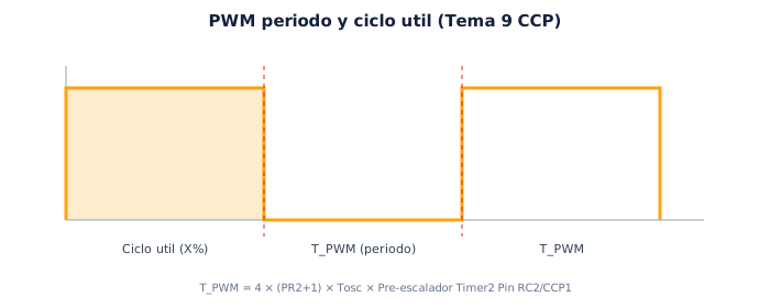
Section titled “What PWM is”PWM (Pulse Width Modulation) repeats a digital waveform: the pin toggles high and low with fixed period T_PWM. You change duty cycle — high time as a percentage of T_PWM — to simulate analog power to a motor or LED.
Step 1 — Period and duty
Section titled “Step 1 — Period and duty”| Parameter | Symbol | What it controls |
|---|---|---|
| Period | T_PWM | Frequency F_PWM = 1/T_PWM |
| Duty cycle | X % | High time / T_PWM |
| Resolution | effective bits | How many duty steps you can program |
Step 2 — Three CCP modes
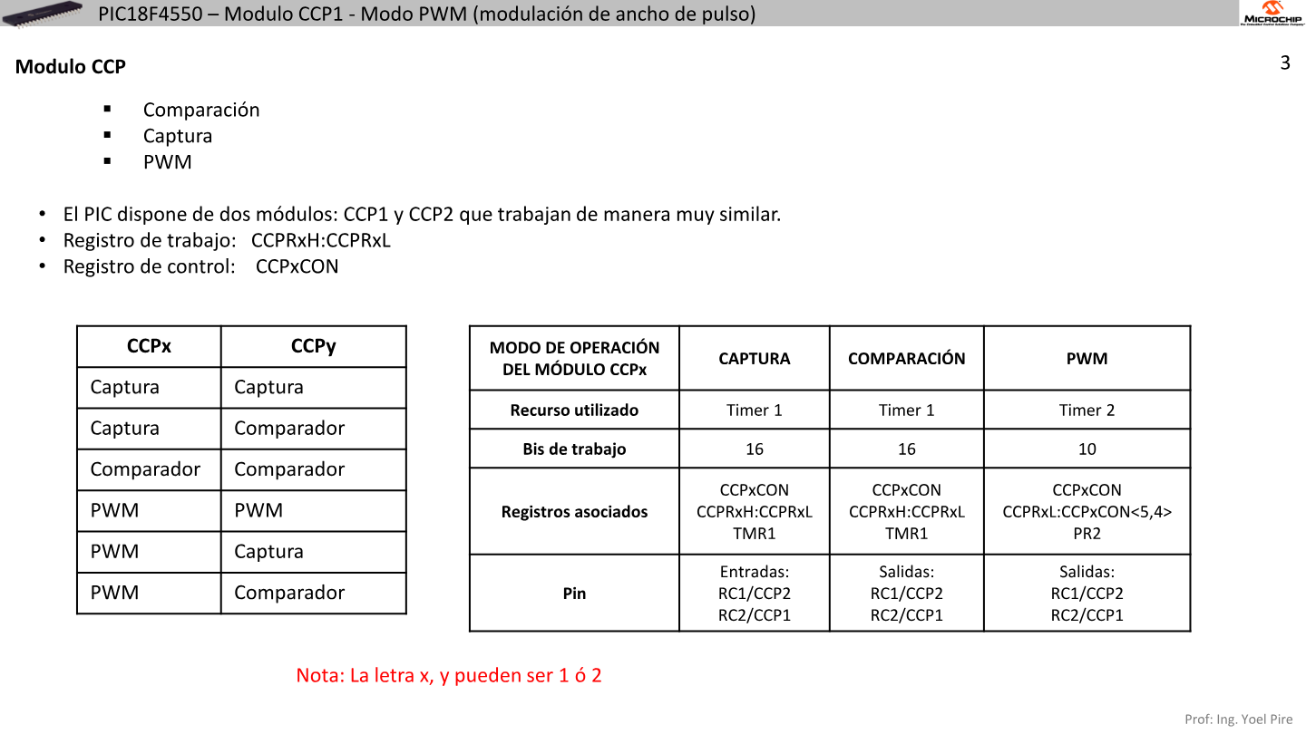
Section titled “Step 2 — Three CCP modes”| Mode | Timer base | Use |
|---|---|---|
| Capture | Timer1 | Measure pulse width / frequency |
| Compare | Timer1 | Trigger at precise instant |
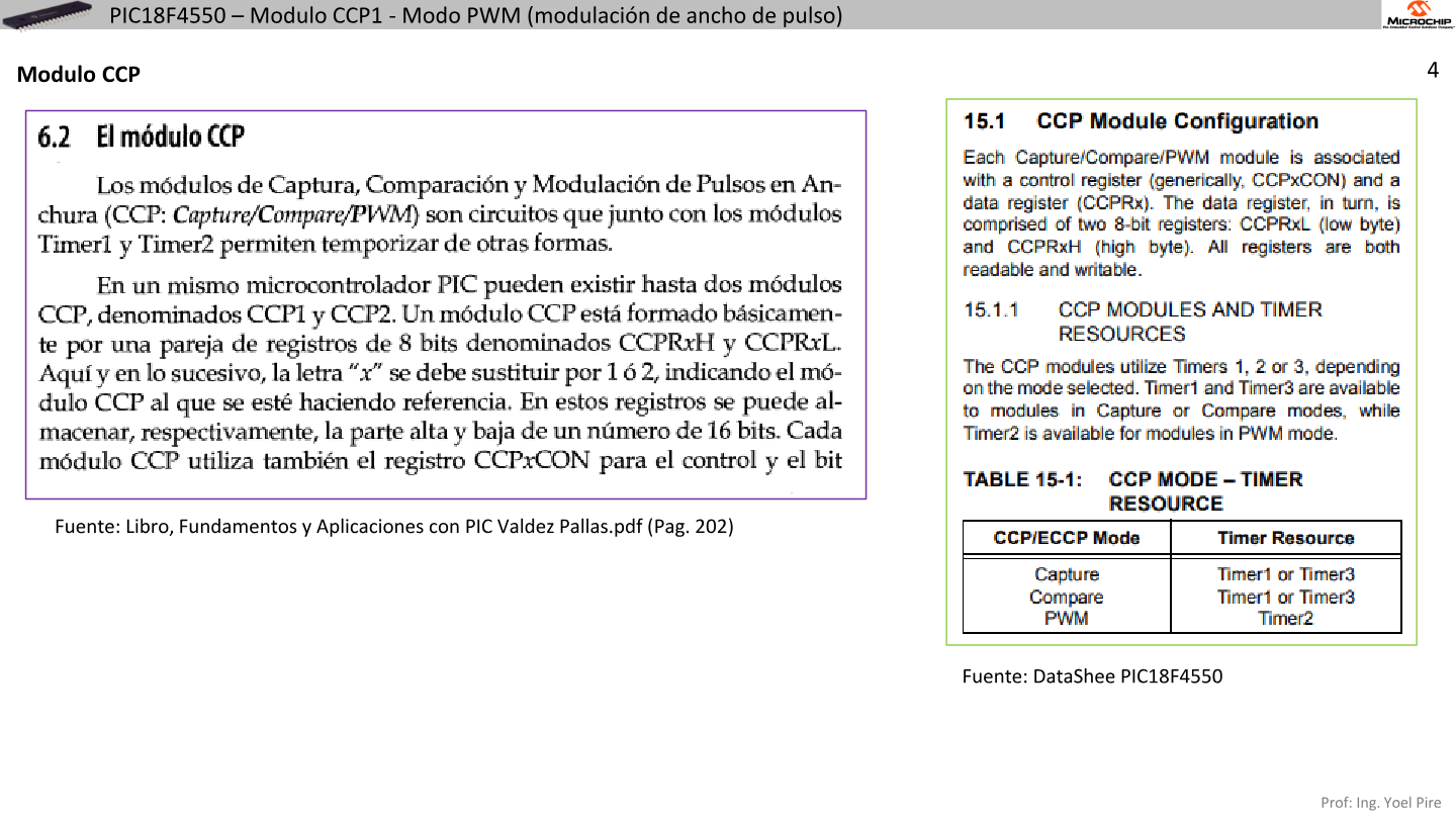
| PWM | Timer2 + PR2 | Motor, LED, servo — course focus |
Capture/compare are covered in Timer 1; PWM uses Timer2 separately.
Step 3 — Key PWM registers
Section titled “Step 3 — Key PWM registers”| Register | Function |
|---|---|
PR2 | Period — TMR2 counts 0 → PR2 → reset |
T2CON | Timer2 prescaler, TMR2ON |
CCPR1L + CCP1CON<5:4> | Duty cycle (10 bits on PIC18) |
CCP1CON | CCP mode — PWM = CCP1M3:0 = 1100 → 0x0C |
Step 4 — Hardware output
Section titled “Step 4 — Hardware output”With CCP1CON = 0x0C and Timer2 active, RC2 toggles automatically — no BSF LATC, 2 loop needed. Set BCF TRISC, 2 (output) once at init.
Topic 9 formulas
Section titled “Topic 9 formulas”PWM period:
T_PWM = 4 × (PR2 + 1) × Tosc × Timer2_PrescalerDuty cycle (value to load):
CCPR1L : CCP1CON<5:4> = (T_PWM × X%) / (Tosc × Prescaler)Resolution (effective bits):
log2( Fosc / (F_PWM × Prescaler) )With Fosc = 20 MHz, Timer2 prescaler = 1:4, F_PWM = 5 kHz:
PR2 = 1 / (5 kHz × 4 × Tosc × 4) − 1 = 249 50% duty → CCPR1L = 124PWM setup — 5 steps
Section titled “PWM setup — 5 steps”BCF TRISC, 2— RC2/CCP1 as output- Load
PR2for target frequency - Configure
T2CON(prescaler, TMR2ON = 1) - Load
CCPR1Land DC1B1:DC1B0 inCCP1CONif needed CCP1CON = 0x0C— PWM mode
Full example — 5 kHz, 50% duty @ 20 MHz
Section titled “Full example — 5 kHz, 50% duty @ 20 MHz”config_pwm_5khz_50: BCF TRISC, 2 ; RC2 output (CCP1) MOVLW D'249' MOVWF PR2 ; period ~5 kHz, PS=1:4 MOVLW D'124' MOVWF CCPR1L ; duty ~50% MOVLW B'00001101' ; TMR2ON, prescaler 1:4 MOVWF T2CON MOVLW 0x0C ; CCP1 PWM mode MOVWF CCP1CON RETURNTo change motor speed: modify CCPR1L (duty) without recalculating PR2 if PWM frequency stays the same.
CCP1 vs CCP2
Section titled “CCP1 vs CCP2”| Module | Pin | Practice |
|---|---|---|
| CCP1 | RC2 | Practice 4 PWM, Practice 6 motor |
| CCP2 | RC1 | Second PWM output if design requires |
Both in PWM mode share Timer2 and PR2 — same frequency, different duty in CCPR1L / CCPR2L.
Common mistakes
Section titled “Common mistakes”| Mistake | Consequence |
|---|---|
| PWM without TMR2ON | RC2 idle |
| Skip TRISC | Pin does not drive |
CCP1CON in capture mode | No PWM waveform |
| Wrong PR2 | Unexpected frequency |
| Mix Timer1 with PWM | Capture uses T1; PWM uses T2 |
UNEXPO practices
Section titled “UNEXPO practices”Practica · Laboratory
Practice 4 — PWM
Calculate PR2 and CCPR1L, configure Timer2 and CCP1, connect load on RC2. Tutorial: Practice 4.
Practica · Laboratory
Practice 6 — Stepper motor
Use PWM or coil sequence to drive the motor. Requires correct CCP/Timer2 setup. Tutorial: Practice 6.
Next step
Section titled “Next step”- ADC — read potentiometer to adjust duty live (optional in Practice 4)
- Partial III — timers + PWM review
- Quick guide — PWM/CCP
Exam-style questions
Section titled “Exam-style questions”Which timer does CCP PWM use?
Timer2 with period register PR2.
What value typically sets CCP1 to PWM mode?
CCP1CON = 0x0C (mode bits 1100).
Which pin outputs CCP1?
RC2.
For 50% duty with PR2 = 249, CCPR1L ≈ ?
124 (half the period in duty counts).
Ejercicio · Parcial
Calculate PR2 for F_PWM=5kHz, Fosc=20MHz, prescaler 1:4
PR2 = 1/(5kHz) / (4 × 1/20MHz × 4) − 1 = 249 per the UNEXPO Microcontrollers course example.
PWM and CCP module
Based on: Clase Tema 9. Modulo CCP (PWM).pdf
0 of 0 answered
Sign in with CALETAS to sync this result across devices.
Sign in with CALETAS